載入中…

Teaching Resources / Level 3 · Innovate / Unit 4
Assessment: Vector diagram practice, oral Q&A, worksheet
PPT (coming soon)
Background knowledge from Chapter 2 of this unit's Teacher's Guide. Use it with the interactive lessons below in class.
This section is written for lesson preparation. It explains the fluid dynamics terms and physics concepts used in this unit in plain language, so teachers can draw on them in class at any time.
In plain terms: when you ride a bicycle on a calm day, you still feel wind on your face. That is the relative wind created by your own forward motion. A spinning wind turbine blade does not feel just the natural wind; it feels the relative wind, the combination of the natural wind velocity vector and the (reversed) blade rotation velocity vector.
Vector formula:
V_rel = V_wind + (-V_blade)
Where:
Teaching focus: the blade tip moves very fast, so the relative wind at the tip is very strong and almost parallel to the rotor plane. Near the root, the blade moves slowly, so the relative wind comes in at a steeper angle (closer to the direction of the natural wind).
In plain terms: when the relative wind flows over a blade with a specially shaped airfoil, the upper and lower surfaces are asymmetric, so the air moves at different speeds and creates a pressure difference. The resulting force can be split into two directions:
1. Lift: the force perpendicular to the relative wind. On a wind turbine, it has a forward component and is the main force that pulls the blades around to generate electricity.
2. Drag: the force parallel to the relative wind. On a wind turbine, it is a harmful force that tries to bend the blades backward. It wastes energy and adds load on the tower.
Key analogy: imagine putting your hand out of a car window.
In plain terms: the angle of attack is the angle between the direction of the relative wind and the blade's chord line (the line from the leading edge to the trailing edge of the blade's cross-section). It is a dynamic angle: when the wind speed or blade speed changes, the angle of attack changes too.
How angle of attack relates to lift:
Stall: when the angle of attack becomes too large (for example, a sudden strong gust changes the angle of the relative wind), the airflow can no longer follow the blade surface and separates from it. Lift drops suddenly and drag rises sharply. This is called stall.
Teaching focus: engineers must make sure the blades stay at the best angle of attack across a range of wind speeds to avoid stall. That is why modern wind turbines have a pitch system that adjusts the blade angle automatically.
In plain terms: as the name suggests, it is lift divided by drag.
Formula:
Lift-to-drag ratio = L / D = lift / drag
Typical values:
| Object | Typical lift-to-drag ratio |
|---|---|
| Flat plate (drag-based windmill) | < 1 |
| Modern wind turbine blade | 80 ~ 120 |
| Glider | 40 ~ 60 |
| Airliner | 15 ~ 20 |
Teaching focus: this is the most important measure of a blade's aerodynamic efficiency. The ultimate goal of modern blade design is to maximize the lift-to-drag ratio, so the useful force that turns the rotor is far greater than the drag that wastes energy. The higher the lift-to-drag ratio, the more efficient the turbine.
In plain terms: a sailboat running straight downwind is pushed along by the wind's drag, so it can never go faster than the wind. So how can the tip of a wind turbine blade move at 6 to 8 times the wind speed?
Because the blade behaves like a sailboat sailing across the wind. When a boat sails at an angle to the wind, the lift from its sail has a forward component that drives the boat. As long as the lift-to-drag ratio is high enough and drag is small enough, the boat's speed (or the blade's speed) can keep building and exceed the natural wind speed.
Key insight:
Put more simply: how does the wind act on a turbine to make it start turning? Or, what kind of force makes it turn?
The physics:
1. As the relative wind flows over the blade's airfoil, it produces lift and drag.
2. Lift is perpendicular to the relative wind; drag is parallel to it.
3. Adding the lift and drag vectors gives a resultant force.
4. This resultant force can be split into two components:
5. To maximize the rotational component, the angle of attack must be carefully designed so the lift points in the direction that gives the largest rotational component.
This set of teaching aids has five parts: Series Aid 1, Series Aid 2, Aid 3, Aid 4 and Aid 5.
Basic equipment:
Three demonstrations:
Demonstration 1: Airplane takeoff
Fit the airplane's center-of-mass pivot into the hole at the top of a seesaw stand, and add a counterweight to the other end so the airplane and counterweight are roughly balanced (with the airplane slightly heavier). Then lift the stand and walk forward; the relative wind makes the airplane take off. Slip on the explanation board and explain: the airplane takes off because lift overcomes gravity.
Demonstration 2: Land sail cart
Remove the airplane from the seesaw stand and mount it on the base of a land sail cart. The base can rotate, so when the cart meets a crosswind, the airplane automatically adjusts its orientation so the wing generates lift, and the cart moves forward. Friction from the wheels stops the cart from sliding sideways.
Demonstration 3: Wing windmill
Remove the airplane from the sail cart and tape its wing to the platform on the windmill shaft. Simply walk forward with the windmill and the relative wind will make it turn.
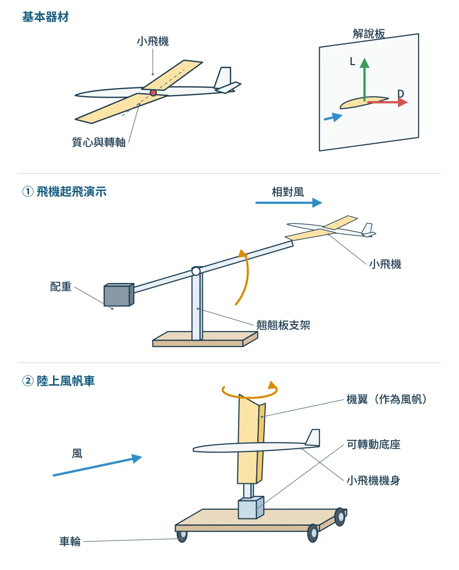
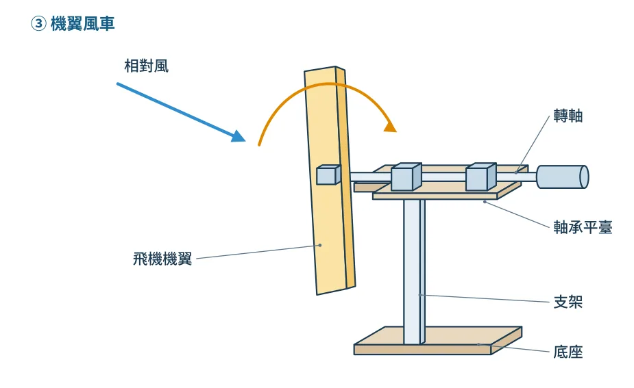
Teaching purpose: show clearly that airplanes, sailboats and wind turbine blades all experience lift under the same conditions and all work by using lift; they just use it in different ways.
Equipment:
Procedure:
1. Insert the wing-shaped piece into the sail cart and expose it to a crosswind; the cart moves forward.
2. Turn off the wind and hook an elastic cord onto the wing-shaped blade to represent the force it feels in the wind.
3. When the wing-shaped piece is pulled in the direction of the resultant force shown on the diagram board, the cart does indeed move forward.
4. Remove the wing-shaped piece and insert it into the windmill's shaft connector, held in place by a magnet. In the same wind, the windmill turns.
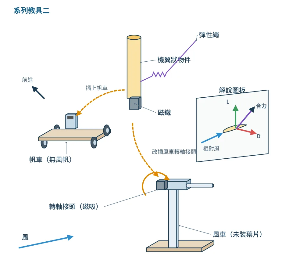
Teaching purpose: give more direct evidence that a sail cart's sail and a windmill's blade experience lift and drag in the same way, and that the resultant force makes them move forward or turn in the same way.
Use an elastic cord to simulate the resultant force that turns the windmill. First let the wind turn the windmill and explain the lift, drag and resultant force on the blades. Then turn off the wind and use the elastic cord to pull in the same direction as the resultant force; the windmill turns just the same.
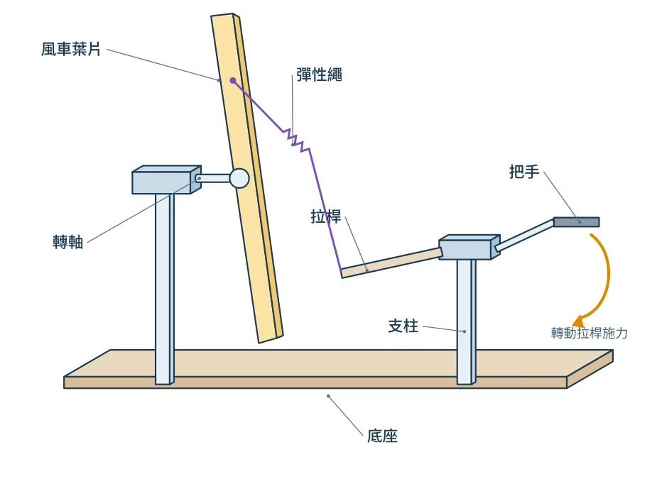
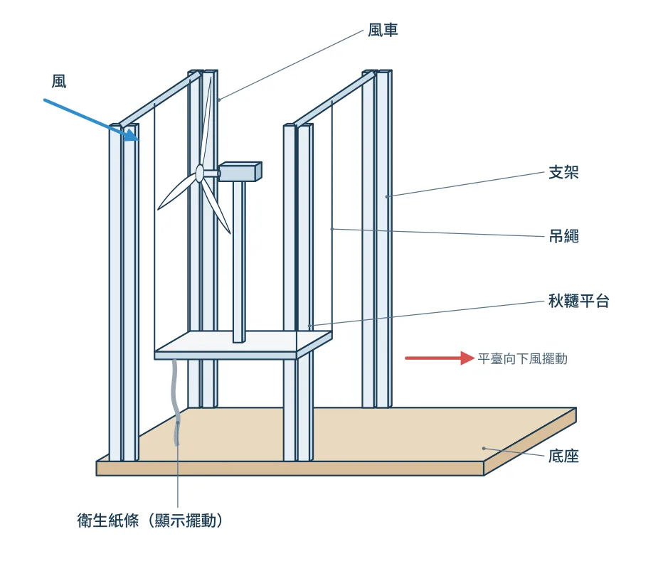
Teaching purpose: provide hands-on evidence that when a windmill turns, its blades really do experience lift and drag, and that only a small part of these forces drives the rotation. Most of the force points downwind (that is, the whole windmill experiences a large downwind force).
Setup and procedure:
1. Place the windmill on a swing-like platform.
2. Clamp the windmill shaft so it cannot turn.
3. Blow on the windmill with an electric fan; the swing platform swings back only slightly.
4. Release the clamp and the windmill starts spinning quickly.
5. Now the lift and drag on the blades, acting in their particular directions, produce a large downwind component, and the swing platform swings back much farther.
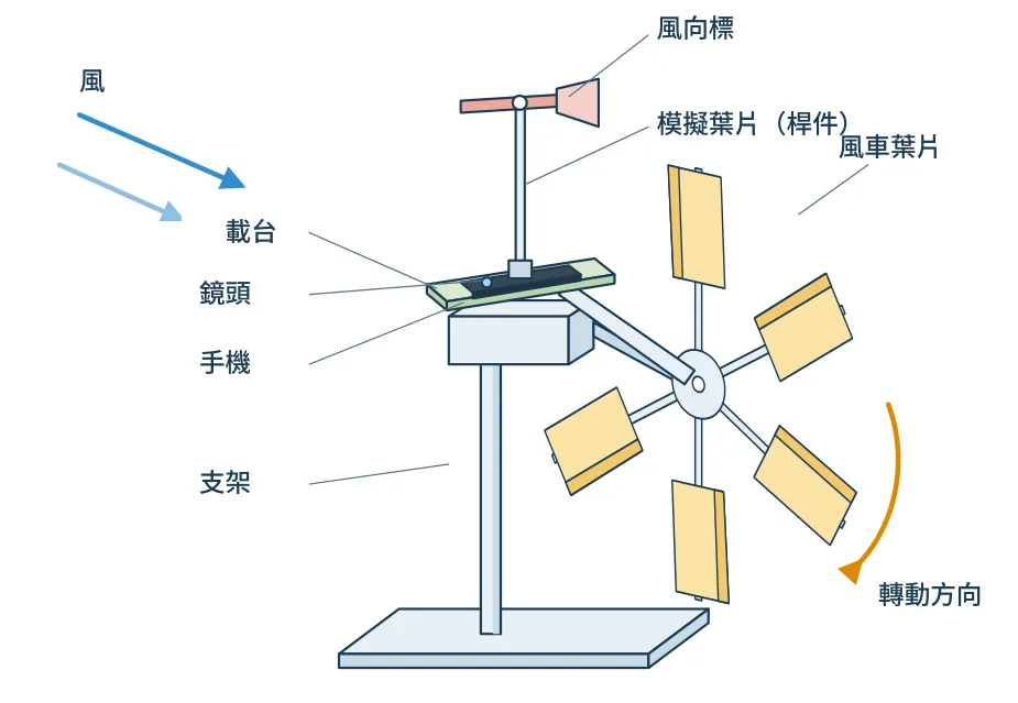
Teaching purpose: provide clear evidence that the relative wind felt by a spinning blade is actually closer to parallel with the rotor plane.
Setup and procedure:
1. A rod fixed to the rotating shaft represents a blade.
2. A wind direction indicator is mounted on the rod.
3. A phone is mounted on a platform fixed to the rotating shaft, with its camera aimed at the wind direction indicator.
4. The shaft is driven by a wind turbine rotor.
5. Through a video call to a second phone, you can watch from outside, in real time, what the spinning phone sees.
Result: this confirms that the relative wind felt by the blade does tend to be parallel to the rotor plane.
Every slice of the blade travels in a circle. The closer to the tip, the bigger the circle and the faster it moves: the speed ωr grows with the radius r.
Set the blade angle θ at three control points; a smooth curve joins them.
Here the blade speed ωr = 16.8 m/s and the relative wind V_rel = 18.6 m/s. At a fixed tip speed ratio, changing the wind speed changes the sizes, not the angles.
Simplified model, not experimental dataHere the angle of attack is 17.5°, beyond about 15°: the air separates from the suction side (stall), lift drops and drag soars.
Goal: keep the angle of attack within 4°–10° from 20% to 100% span. Not yet: current range 0.1° to 27.1°; only 29% of the span is on target. Hint: the angle of attack in the root section is off target; make θ there larger.
Angle of attack α along the span (root → tip)
Current: Design your ownCompare: Twisted blade
Your design: angle of attack from 0.1° to 35.6° along the span (27.5° at 20%, 0.1° at the tip).
Local speed ratio λ_r = λ × r/R = 7.0 × 0.30 = 2.10
Inflow angle φ = atan(1/λ_r) = atan(1/2.10) = 25.5°
Angle of attack α = φ − θ = 25.5° − 8.0° = 17.5°
Twist design: θ = φ − α_opt (α_opt ≈ 6°) → ideal θ here = 19.5°
Turning force = L·sinφ − D·cosφ; thrust = L·cosφ + D·sinφ. The smaller φ is (nearer the tip), the more of the lift becomes thrust.
Key: V is the natural wind, −ωr the head-on wind from the blade’s motion, V_rel the relative wind; lift is perpendicular to the relative wind and drag parallel to it (drag drawn 5× larger); dashed arrows are the turning force and thrust.
Related units: Junior High Unit 9; Senior High Unit 4
One question per stage: read it, choose an answer, then press Check answer.
Loading questions…
Related units: All units at all three levels